ë
Engineering Design, Reverse Engineering & DFM Optimization
3D Simulation, Advanced Error Detection, and Nesting to Maximize Material Yield Before Fabrication.


Smart Design: Bridging the Gap Between Concept and Cost-Effective Production
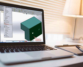
LaserSpike’s engineering department utilizes advanced CAD/CAM software including SolidWorks, Catia, AutoCAD, and CorelDraw to deliver detailed 3D modeling, reverse engineering, and sheet metal optimization. We understand that not every client is an expert in metal fabrication constraints, such as bend deductions, heat distortion, or tooling limitations. Our dedicated design team conducts a thorough Design for Manufacturing (DFM) review for every blueprint before production, eliminating geometry errors to save your time, lower costs, and secure premier structural quality.
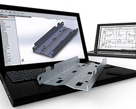
Leveraging the intelligent BySoft (Switzerland) software ecosystem, our engineers convert 3D CAD files into optimized CNC code, deploying data through our central server directly to the fiber laser and press brake machinery. This automated data transfer fully eliminates manual setup errors on the shop floor.
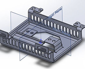
Flat Pattern & Bend Allowance
Integrating our Bystronic press brake tooling database, BySoft automatically calculates precise flat patterns based on material gauge, tensile strength, and exact bend radii. The system flags any holes or slots positioned too close to bend lines with color-coded alerts, allowing our designers to adjust geometries before laser cutting to prevent hole elongation during active forming.
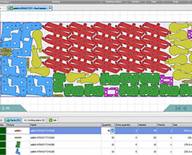
Intelligent Nesting
Our software runs advanced nesting algorithms to tightly pack components onto standard sheet sizes (1×2, 1.25×2.5, or 1.5×3 meters), minimizing skeleton scrap and optimizing sheet yield. The nesting system utilizes 5-degree freedom tracking to interlock complex geometries. Additionally, the software monitors sheet grain direction (rolling direction) to protect components requiring strict structural bending integrity, while seamlessly routing small parts onto off-cut remnants to lower raw material expenses.
Laser Path Optimization
Converting raw drawings into clean cutting files involves complex path optimizations. The software algorithm configures specific lead-ins, micro-joints, and cutting sequences to minimize head travel time, prevent local heat accumulation on the sheet, and eliminate collision risks between the laser head and tipped parts.
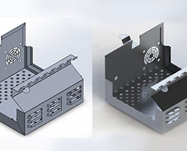
Tolerance & Assembly Fit Checks
Separate sub-components (such as an enclosure body and its door) are thoroughly inspected in a virtual 3D assembly environment before fabrications. Our engineers check hole alignments, movement clearances, interference radii, and even account for dry film thickness parameters of electrostatic powder coating. We maintain a strict tolerance of ±0.2 mm for dimensions up to 50 mm, and actively optimize tolerances for parts up to 2000 mm to ensure smooth shop floor assembly.
The golden rule of DFM: Bending-over-Welding Optimization
A golden law governed by modern DFM states: Maximize bending, minimize welding. While arc welding is an essential joining method, an experienced designer replaces complex weld joints with smart multi-bend profiles, integrated stiffeners, or self-locking tabs. This approach drops fixture costs, eliminates post-weld deburring, and enhances structural strength. Our integrated Bystronic simulation suite allows us to analyze bending sequences early on, providing you with the most economical manufacturing path.
×
Our Capabilities
At Spike, we offer an end-to-end suite of sheet metal engineering and fabrication services. From design, 3D modeling, and fiber laser cutting to high-precision CNC bending, expert welding, powder coating, and final assembly. Whether you require a single functional prototype or high-volume industrial production, our engineering team ensures your drawings are executed with maximum precision, speed, and manufacturing flexibility.
Gallery
Explore our gallery to see how Spike transforms technical drawings into high-quality metal components. Every project displayed here reflects our commitment to robust engineering, and flawless finishes—ranging from delicate industrial prototypes to large-scale architectural structures.
About Us
Spike is a premier provider of advanced sheet metal design and fabrication solutions. We simplify and accelerate your production cycle. Whether your project demands complex industrial enclosures or bespoke architectural metalwork, uncompromising precision is our signature standard.
Contact Us
EF
Address: No. 1, Block 24, Amirkabir Industrial Zone, Imam Khomeini Ave, Isfahan, Iran
Email: info@LaserSpike.com
Telegram: @SelSpike
Instagram: @LaserSpike
Central Hotline
+98 31 9100 4020
Sales & Engineering Support
+98 31 3131 5943 | +98 31 3131 5944
+98 31 9501 7300 | +98 31 9501 7500
RFQ & File Submission (Telegram / WhatsApp)
+98 905 752 0383
Management:+98 912 671 6499
+98 913 796 2046
+98 913 323 9059
How to Order
Easy online ordering from anywhere across the country. Simply send your technical drawings or CAD files via Telegram or Eitaa.
Contact: +98 905 752 0383
Sheet Metal Design Guide
Adhering to Design for Manufacturing (DFM) principles empowers engineers and designers to create highly functional, manufacturing-ready sheet metal parts. Following these technical guidelines minimizes unnecessary production costs and eliminates material waste.
To ensure your custom designs are fully optimized for seamless production, we highly recommend reviewing our comprehensive engineering standards.
Laser Cut Patterns
A comprehensive collection of custom graphic patterns optimized for decorative laser cutting is available in our exclusive archive.
To get a rapid price quotation, simply select your preferred pattern code from the journal below and send it to us along with your required dimensions.